 |  |  |  |  |
 |  |  |  |  |
 |  |  |  |  |
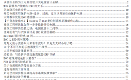
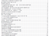
历经半个多月时间,终于把第四部整理完毕。先上传供各位电源工程师、电源学习人员学习之用,持续更新! 获 详细

| |
| |
| |
| |
| |


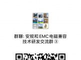
电磁兼容群:334175333
防雷技术群:50395925
安规技术群:559434720
公司地址:陕西省西安市高新区毕原二路军民融合产业园一期B1栋1层101室
联系电话:王媛媛 17791287039
联系电话:桃花岛主 18991808692
电子邮箱:info@emcmark.com
Powered by Discuz! X3.4© 2001-2013 Comsenz Inc. 陕ICP备2022014304号 西安容冠电磁科技有限公司


 提升卡
提升卡 置顶卡
置顶卡 沉默卡
沉默卡 喧嚣卡
喧嚣卡 变色卡
变色卡 显身卡
显身卡 楼主
楼主